ARM Assembly #11 - Memory Block Access(LDM, STM)
In this post, we’ll look at the ARM instructions LDM and STM, which allow reading or writing multiple words at once from memory.
In the previous post, we learned that LDR and STR can only handle a single word at a time.
However, when working with contiguous memory areas such as arrays or structures, repeatedly using LDR or STR becomes inefficient.
To solve this problem, ARM provides LDM (Load Multiple) and STM (Store Multiple), which can operate on memory blocks.
Memory Block
In ARM programming, it’s very common to handle a group of contiguous data such as arrays or structures at once.
Inside memory, these data are stored consecutively in word-sized units.
This continuous region is called a memory block.
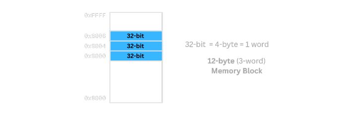
Memory is actually a linear address space, but for visualization, it’s often represented as a 2D grid for clarity.
Each cell represents one word (4 bytes) of storage.
As mentioned in the previous post, we can access memory word by word using hexadecimal addresses.
Inefficiency of Using LDR/STR
Instructions like STR and LDR can only load or store one word at a time.
  mov r0, #0x8000
  mov r1, #0x1
  str r1, [r0]
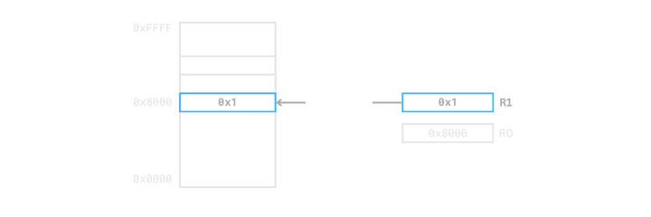
In other words, the relationship between Mem[address] and a register is one-to-one per word.
Although you can manipulate addresses using offsets, you still need to repeat LDR and STR to handle multiple words.
Such repetition is inefficient when dealing with arrays or structures that occupy contiguous memory.
LDM and STM
ARM provides LDM and STM instructions to handle such contiguous memory blocks efficiently.
LDM: Loads multiple words from memory into registers.STM: Stores the values of multiple registers into memory.
  ldm Rn, {registers}
  stm Rn, {registers}
Here,
Rn is the base address of the memory block to access.
{registers} is a list of registers, separated by commas or defined as a range using a dash (-).
We call
Rnthe base address, not the start address, because the actual start address depends on the addressing mode, which we’ll discuss later.
Working with Register Lists
Let’s look at three examples to see how register lists are used.
Although only
LDMis used here,STMworks the same way.
The only difference is thatSTMstores register values into memory instead of loading them.
Example 1) Load two words from memory 0x8000 into R1 and R2
  mov r0, #0x8000
  ldm r0, {r1, r2}
R1← Mem[0x8000]R2← Mem[0x8004]
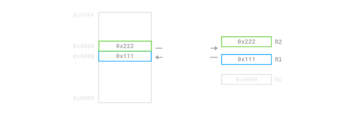
ldm r0, {r1, r2} loads two consecutive words into R1 and R2.
Example 2) Load four words from memory 0x8000 into R1 to R4
  mov r0, #0x8000
  ldm r0, {r1 - r4}
R1← Mem[0x8000]R2← Mem[0x8004]R3← Mem[0x8008]R4← Mem[0x800C]
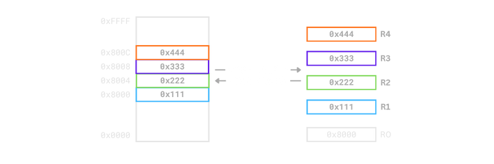
ldm r0, {r1-r4} reads four consecutive words and stores them sequentially in R1 to R4.
Example 3) Load from memory 0x8000 into R1, R2, and R7
  mov r0, #0x8000
  ldm r0, {r1 - r2, r7}
R1← Mem[0x8000]R2← Mem[0x8004]R7← Mem[0x8008]
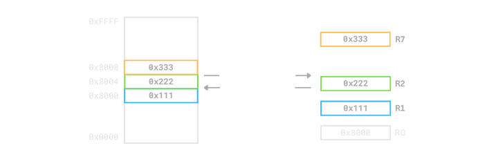
ldm r0, {r1-r2, r7} demonstrates that non-consecutive register lists can be specified.
Auto-Updating the Base Address
  ldm Rn!, {registers}
  stm Rn!, {registers}
Adding ! after the base register Rn automatically updates its value to the next address after the operation.
  mov r0, #0x8000
  mov r1, #0x1
  mov r2, #0x2
  mov r3, #0x3

  stm r0!, {r1 - r3}
  @ r0 = r0 + (3 * 4) = 0x8000 + 0xC = 0x800C
In other words, you can store multiple registers and automatically move to the next memory position in one instruction.
Conclusion
In this post, we looked at the basic ideas behind LDM and STM and learned how to use them. However, LDM and STM also have a concept called addressing modes, which control how memory addresses increase or decrease, and whether the base register is included before or after the access.
Addressing modes make much more sense when explained together with stack memory, so in the next post, we’ll go through them in detail while exploring how the stack works in ARM.
See you in the next post, where we’ll walk through the stack and its addressing modes together.