ARM Assembly #12 - Stack Memory and Addressing Modes
In this post, we will explore how the various addressing modes of LDM and STM are used for PUSH and POP operations on stack memory.
In the previous post, we only covered how to use LDM/STM to read and write multiple words at once.
In this post, we will build on that by connecting addressing modes with the stack structure.
What Are Addressing Modes?
In the previous post, all examples assumed that memory addresses moved upwards (increasing) during LDM/STM execution.
However, in practice, memory addresses may increase or decrease, depending on the situation. You can also control whether the memory block starts at the address pointed to by the base register (Rn) or at the next address.
These two aspects—direction and starting position—are defined by ARM’s addressing modes.
The Four Addressing Modes: IA, IB, DA, DB
ARM’s LDM/STM instructions provide the following four addressing modes.
| Address Mode | Description |
|---|---|
| IA | Increment After |
| IB | Increment Before |
| DA | Decrement After |
| DB | Decrement Before |
Increment / Decrement describe whether addresses move upwards or downwards.
Before / After determine whether the address in the base register (Rn) is included in or excluded from the accessed memory block.
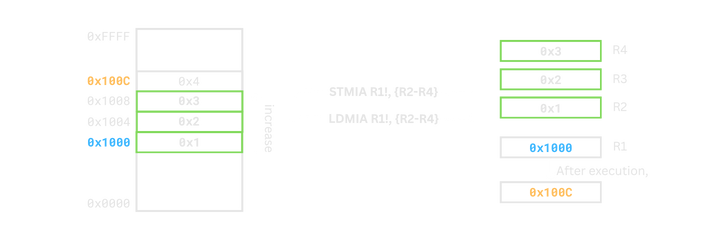
IA (Increment After, Default)
- Increment: moves from a lower address to a higher address.
- After: includes the base address (
Rn) as the starting address.
Address Computation
- start address =
Rn - end adderss =
Rn + (count of registers × 4) − 4 - After execution,
Rn = Rn + (count of registers × 4)
For example, if the register list contains 3 registers and Rn = 0x1000, it works as follows.
0x1008  : end address
0x1004
0x1000  : start address

Rn = 0x100C
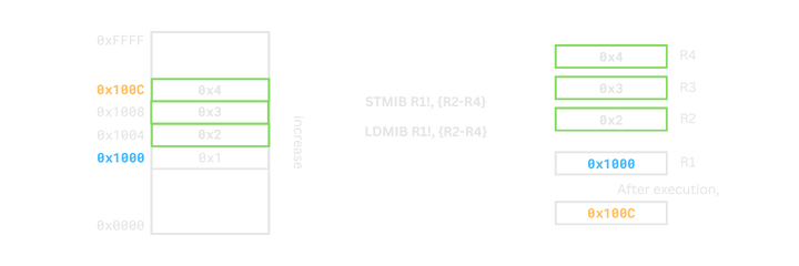
IB (Increment Before)
- Increment: moves from a lower address to a higher address.
- Before: starts from the address immediately after
Rn.
Address Computation
- start address =
Rn + 4 - end address =
Rn + (count of registers × 4) - After execution,
Rn = Rn + (count of registers × 4)
For example, if there are 3 registers and Rn = 0x1000, it works as follows.
0x100C  : end address
0x1008
0x1004  : start address
0x1000

Rn = 0x100C
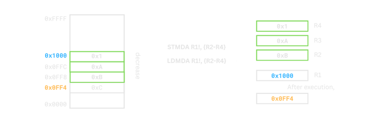
DA (Decrement After)
- Decrement: moves from a higher address to a lower address.
- After: includes the base address (
Rn) as the top of the block.
Address Computation
- start address =
Rn − (count of registers × 4) + 4 - end address =
Rn - After execution,
Rn = Rn − (count of registers × 4)
For example, if there are 3 registers and Rn = 0x1000, it works as follows.
0x1000  : end address
0x0FFC
0x0FF8  : start address
0x0FF4
0x0FF0

Rn = 0x0FF4
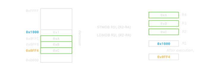
DB (Decrement Before)
- Decrement: moves from a higher address to a lower address.
- Before: starts below the base address (
Rn).
Address Computation
- start addreess =
Rn − (count of registers × 4) - end address =
Rn − 4 - After execution,
Rn = Rn − (count of registers × 4)
For example, if there are 3 registers and Rn = 0x1000, it works as follows.
0x1000
0x0FFC  : end address
0x0FF8
0x0FF4  : start address

Rn = 0x0FF4
How Addressing Modes Are Written in Actual ARM Syntax
It’s important to understand addressing modes conceptually, but in actual ARM assembly, addressing modes are applied as suffixes attached to the instruction.
For example, IA, IB, DA, and DB are written like this:
  ldmia r0!, {r1-r3}
  ldmdb r0!, {r1-r3}
  stmia r0!, {r1-r3}
  stmdb r0!, {r1-r3}
- The two-letter mode (IA/IB/DA/DB) comes immediately after LDM/STM.
In other words, there is no space or dot — the instruction literally becomes LDMIA, LDMDB, etc.
The
!for write-back is separate from the addressing mode In this example:ldmia r0!, {r1-r3}
- IA is the addressing mode (how memory is accessed),
- ! means the base register(
R0) is automatically updated.
STM and LDM with the Same Addressing Mode
Now let’s see how data moves between memory and registers when STM and LDM use the same addressing mode.
mov r0, #0x8000
mov r1, #0x1
mov r2, #0x2
mov r3, #0x3
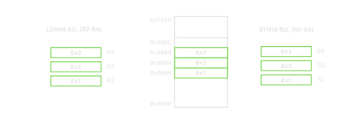
stmia r0, {r1-r3}
mov r1, #0
mov r2, #0
mov r3, #0
ldmia r0, {r1-r3}
In this case, since both STMIA and LDMIA use the same addressing mode,
they store data into a memory block and then read back from the exact same addresses.
However, stack memory does not operate this way. In a stack, PUSH and POP proceed in opposite directions, so you cannot simply use the same addressing mode.
Stack-Specific Addressing Modes: FD, FA, ED, EA
ARM introduces stack-specific names—FD, FA, ED, EA—for handling stack operations. These are not new behaviors, but aliases of IA/IB/DA/DB, renamed from a stack perspective.
| Stack Mode | Description |
|---|---|
| FD | Full Descending |
| FA | Full Ascending |
| ED | Empty Descending |
| EA | Empty Ascending |
Full / Empty indicate whether the stack pointer (SP) points to a full location (last stored data) or an empty slot after PUSH/POP.
Ascending / Descending describe whether the stack grows toward higher addresses (Ascending) or toward lower addresses (Descending) when pushing.
Example: PUSH on an FD Stack
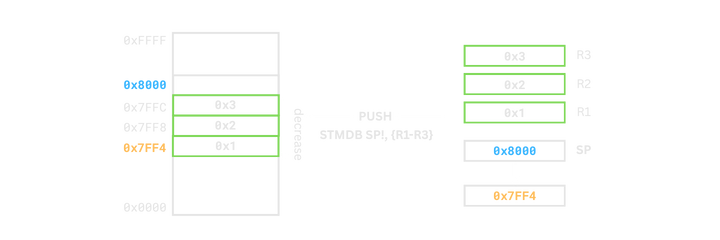
The most common stack structure in ARM is the Full Descending (FD) stack. PUSH on an FD stack can be implemented as follows.
  mov sp, #0x8000
  mov r1, #0x1
  mov r2, #0x2
  mov r3, #0x3

  stmdb sp!, {r1-r3}
  @ R1 -> [0x7FF4], R2 -> [0x7FF8], R3 -> [0x7FFC]
  @ sp = 0x7FF4
Here, stmdb sp!, {r1-r3} behaves the same as stmfd sp!, {r1-r3} in terms of stack mode naming.
The SP moves from 0x8000 to 0x7FF4.
The actual memory locations used are as follows.
| Address | Value |
|---|---|
0x7FF4 |
0x1(R1) |
0x7FF8 |
0x2(R2) |
0x7FFC |
0x3(R3) |
Example: POP on an FD Stack
Now let’s see how to restore values from an FD stack using POP.
  @ Assume STMDB sp!, {r1-r3} has already been executed.

  ldmia sp!, {r1-r3}
On an FD stack, POP is implemented as ldmia sp! in general addressing mode terms, or ldmfd sp! in stack mode naming.
The load order is as follows.
| Address | Register |
|---|---|
0x7FF4 |
R1 |
0x7FF8 |
R2 |
0x7FFC |
R3 |
After the POP, the SP returns to 0x8000.
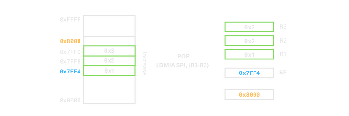
Thus, in an FD stack, using STMDB for PUSH and LDMIA for POP ensures that both operations work correctly on the same stack memory block.
Comparison: Normal Address Modes vs Stack Address Modes
As we have seen, stack address modes are essentially aliases attached to IA/IB/DA/DB.
For STM (PUSH)
| Non-stack Address Mode | Stack Address Mode |
|---|---|
| IA | EA |
| IB | FA |
| DA | ED |
| DB | FD |
For LDM (POP)
| Non-stack Address Mode | Stack Address Mode |
|---|---|
| IA | FD |
| IB | ED |
| DA | FA |
| DB | EA |
In real ARM code, you will often see stack modes like STMFD, LDMFD,
but it is also common to use general addressing modes directly, such as STMDB sp! and LDMIA sp!.
Whichever syntax you choose, the behavior is the same, so at the tutorial stage it is more important to become comfortable with the general addressing modes.
Summary
In this post, we explored what addressing modes in LDM and STM mean and how they are related to stack PUSH and POP operations.
Addressing modes are not just syntactic options; they are tools for precisely controlling the direction and range of memory access.
Once you understand them, you can use LDM/STM far more flexibly, not only for stacks but also for various memory block operations.
In the next post, we will look at the branch instruction B, which controls the flow of execution.