ARM Assembly #9 - Memory Access with Automatic Address Calculation using pre-index and post-index
When accessing memory in ARM assembly, simply using [R1] as an address is often not enough.
When dealing with arrays or buffers stored in consecutive memory, repeatedly updating the base register using ADD can be inefficient.
To solve this, ARM provides an automatic address calculation mechanism through pre-index and post-index modes. In this post, we’ll clearly explain how these modes work, how they differ, and explore how the CPU handles address calculation internally with real assembly examples.
Why do we need pre-index and post-index?
In the previous post, we discussed the basic offset addressing mode using [Rn, #offset].
In that form, the CPU simply calculates an address by adding a fixed offset to the base register Rn and accesses memory at that address.
However, this calculation happens each time the instruction runs,
and the base register Rn itself does not get updated automatically.
In this post, we’ll take it one step further and explore automatic address calculation, the pre-index and post-index addressing modes.
These modes allow the CPU to automatically update Rn during execution,
improving both performance and code compactness when working with repetitive memory accesses.
When accessing memory, the CPU first evaluates the expression inside the brackets to obtain the actual address.
For example, LDR R0, [R1] loads the value stored at the address in R1.
However, when reading consecutive data such as arrays, an additional ADD R1, R1, #4 instruction is required each time.
This increases instruction count and reduces performance.
To address this, ARM integrates automatic address calculation into LDR and STR instructions,
allowing the CPU to perform the address update itself, improving both performance and pipeline efficiency.
![[Offset vs Pre vs Post] Addressing modes overview](/assets/img/pre-post-offset.png)
What is automatic address calculation?
Automatic address calculation is a feature where the CPU automatically increments or decrements the memory address
during the execution of a load or store instruction.
There are two main modes for this: pre-indexing and post-indexing.
The pre-index mode
The pre-index mode means that the CPU updates the base register before accessing memory.
In the form [Rn, #offset]!, the CPU calculates Rn + offset, writes it back to Rn, and then uses that address to access memory.
For example:
ldr r0, [r1, #4]! @ add 4 to R1, then load from the new address
Execution steps:
- R1 ← R1 + 4
- R0 ← Mem[R1]
The post-index mode
The post-index mode performs the memory access before updating the base register.
In [Rn], #offset, the CPU first accesses memory using Rn, then adds the offset afterward.
For example:
ldr r0, [r1], #4 @ load from R1, then increment R1 by 4
Execution steps:
- R0 ← Mem[R1]
- R1 ← R1 + 4
Comparing memory access and address update timing
Although both modes ultimately change Rn by adding the same offset, their behavior differs depending on when the update occurs.
ldr r0, [r1, #4]!   @ pre-index: update R1 before accessing memory
ldr r0, [r1], #4    @ post-index: access memory first, then update R1
- In pre-index,
R1is updated before memory access. - In post-index,
R1is updated after memory access.
Thus, pre-indexing is used when you want to access the next element first, while post-indexing is useful when you need to access the current element before moving on.

Example test using GCC, QEMU, and GDB
Here’s a minimal example comparing both modes. You can build and debug it using GCC, QEMU, and GDB as follows.
pre-post.s
  .text
  .global _start
_start:
  ldr r1, =array
  ldr r0, [r1, #4]!   @ pre-index: R1 ← R1+4 then, load
  ldr r2, [r1], #4    @ post-index: R2 ← Mem[R1], then R1 ← R1+4
  b .
array:
  .word 0x11111111
  .word 0x22222222
  .word 0x33333333
  .word 0x44444444
Build & Run QEMU
$ arm-none-eabi-gcc \
-nostdlib \
-march=armv4 \
-Ttext=0x10000 \
pre-post.s \
-o pre-post.elf
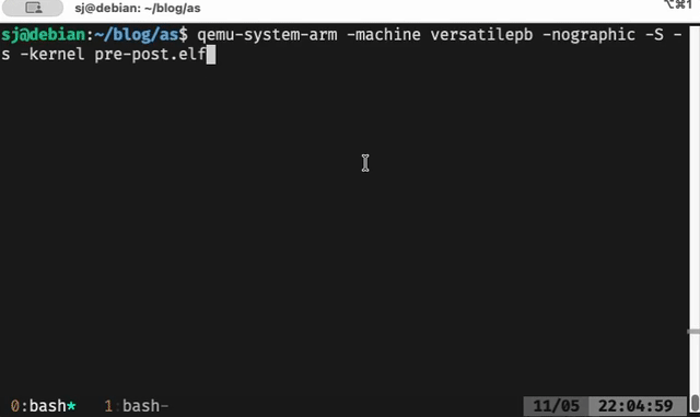
$ qemu-system-arm \
-machine versatilepb \
-nographic \
-S -s \
-kernel pre-post.elf
Debug with GDB
$ gdb-multiarch pre-post.elf

(gdb) target remote :1234    # Connect to GDB server
(gdb) i r r0 r1 r2           # Show registers, R0, R1, R2
(gdb) x/4w 0x10010           # Print 4 words at 0x10010(address of array)
R1 value changes during GDB step execution — pre-index updates first, post-index after.After running step-by-step in GDB,
you’ll see that R1 changes to array+4 after the pre-index instruction,
and to array+8 after the post-index instruction.
Hardware-level perspective
Inside the CPU, each instruction passes through multiple pipeline stages. Typically, address calculation happens in the Execute stage via the ALU, and memory access occurs in the Memory stage.
- In pre-index, the address is calculated first (Execute) and then used for access (Memory).
- In post-index, memory access happens first, then the base register is updated (Write Back).
This hardware design allows the CPU to update addresses automatically without additional ADD instructions, reducing instruction count and improving pipeline throughput for repetitive memory operations.
Conclusion
Both pre-index and post-index modes automate address updates, and their only difference lies in whether the update occurs before or after memory access.
Use pre-index when you need to move to the next element before accessing it, and post-index when you want to access the current element first.
In the next post, we’ll extend this idea to stack operations and explore how LDM/STM can load or store multiple registers efficiently.