ARM Assembly #10 - Understanding Stack Memory in ARM
Today, we’ll learn about stack memory, which the CPU uses to handle temporary data.
Building on what we learned about memory access instructions in previous posts, we’ll prepare for the next topic — block memory access using LDM and STM.
Previous Posts:
What Is Temporary Data?
Temporary data refers to information that is created and destroyed during program execution. Typical examples include local variables, function parameters, and return addresses used in function calls. Because these values exist only temporarily, they don’t need to occupy memory for the entire program runtime.
ARM Memory Layout
Even temporary data must be stored in memory before the CPU can process it. Memory is typically divided into several regions based on purpose:
- Code Segment: where executable instructions are stored.
- Data Segment: where global and static variables are stored.
- Heap Segment: where dynamically allocated data is stored.
- Stack Segment: where function calls and local variables are stored.
Among these, the code and stack segments are essential; in this post, we’ll focus on the stack.
![[AAPCS32] Memory Categories](/assets/img/aapcs32-memory-categories.png)
What Is a Stack?
A stack is literally a structure that “stacks” data. It’s a type of data structure widely used across many areas of computer science.
Basic Stack Operations: PUSH & POP
A stack supports two key operations — PUSH, which adds data, and POP, which removes it. PUSH places data onto the top of the stack, and POP retrieves the most recently added item.
Stack vs Queue
A stack can be imagined as a pile, whereas a queue can be imagined as a waiting line. Both are linear data structures, but they differ in their input/output order.
- Stack (LIFO) — The last element added is the first one removed.
- Queue (FIFO) — The first element added is the first one removed.
The key point of a stack is that it processes the most recent data first. This property makes it especially useful for managing function calls and local variables.
ARM Stack Memory
Stack memory refers to the memory area that behaves like a stack data structure. In ARM, it’s a continuous region used to store temporary data such as local variables and function parameters.
Structure of ARM Stack Memory
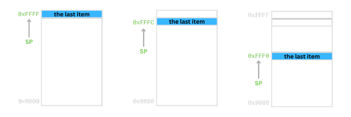
The ARM architecture uses a Full Descending (FD) stack model. This means the stack grows downward in memory, and the Stack Pointer (SP) points to the last stored value.
Note: Four stack model types
- Full Stack: SP points to the last stored item.
- Empty Stack: SP points to the next empty space.
- Descending Stack: Stack grows toward lower memory addresses.
- Ascending Stack: Stack grows toward higher memory addresses.
Therefore, an FD stack grows downward (descending) while SP always points to the topmost (full) item.
Stack Pointer (SP)
Stack memory is still just memory, so it must be accessed through addresses. In the FD model, we must keep track of the most recently pushed data, so a dedicated register is used for that purpose. This register is called the Stack Pointer (SP).
In ARMv4, register R13 is used as the stack pointer.
Implementing PUSH & POP Using LDR and STR
PUSH using STR
The PUSH operation adds data to the stack in two steps:
- Decrease SP by 4.
- Store the value at the new SP location.
  mov sp, #0x80000
  str r1, [sp, #-4]!
Since the stack grows downward, SP must be decreased. Because the ARM stack uses 4-byte words, the SP is decreased by 4 for each push.
POP using LDR
POP removes data from the top of the stack in two steps:
- Load the value at the address pointed by SP.
- Increase SP by 4.
  mov sp, #0x80000
  ldr r1, [sp], #4
Because SP points to the most recent value in the FD model, we first read it, then increment SP to move to the next item.
Example and Debugging
stack-push-pop.s
  .text
  .global _start
_start:
  mov sp, #0x80000
  mov r1, #0x1
  mov r2, #0x2
  mov r3, #0x3

  str r1, [sp, #-4]!
  str r2, [sp, #-4]!
  str r3, [sp, #-4]!

  ldr r0, [sp], #4
  ldr r0, [sp], #4
  ldr r0, [sp], #4

  b .
In this example, we manually set the stack base address to
0x80000. In a real system, the stack pointer is initialized by the linker script or the kernel during process setup.
Build and Run in QEMU
$ arm-none-eabi-gcc -nostdlib -Ttext=0x10000 -o stack-push-pop.elf stack-push-pop.s
$ qemu-system-arm -nographic -machine versatilepb -S -s -kernel stack-push-pop.elf
Debugging with GDB
$ gdb-multiarch stack-push-pop.elf

(gdb) target remote :1234    # connect to GDB server

# Check pushed values
(gdb) x/3w $sp
(gdb) i r r1 r2 r3
(gdb) i r sp                 # SP after STR

# Check popped values
(gdb) i r r0
(gdb) x/3w $sp
(gdb) i r sp                 # SP after LDR
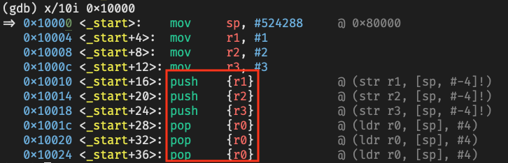
str and ldr instructions automatically shown as push and pop in GDB
Conclusion
In this post, we examined both the concept of the stack and how it works in ARM architecture. The stack plays a crucial role in managing function calls and local variables.
However, when saving or restoring multiple registers, using only LDR and STR becomes inefficient, as shown below:
  mov r1, #0x1
  mov r2, #0x2
  mov r3, #0x3

  str r1, [sp, #-4]!
  str r2, [sp, #-4]!
  str r3, [sp, #-4]!

  @ You must repeat STR for each register you want to store.
As the number of instructions increases, CPU pipeline efficiency decreases.
To solve this problem, ARM provides the LDM (Load Multiple) and STM (Store Multiple) instructions.
In the next post, we’ll explore how to use them for efficient block memory access on the stack.